Theory of Operation
The Door Lock SZED application is a single endpoint sleepy end device that provides simulated door lock deadbolt operation via buttons located on the development board, over-the-air commands, and an optional 3x4 keypad which can be purchased from Adafruit Industries (https://www.adafruit.com/product/1824?gQT=1).
The simulated deadbolt functionality is implemented in src/lock.c. The deadbolt state (locked or unlocked) is maintained in the TR_ZCL_ATTR_DOOR_LOCK_LOCK_STATE_ID Zigbee attribute. Deadbolt movement is simulated over a period of milliseconds defined by TR_LOCK_DEADBOLT_TRAVEL_TIME_MS. This allows for more realistic behavior with regards to ZCL command timing.
Keypad scanning and button 1 and 2 handling is done in src/keypad.c. Button 1 is used to simulate a manual thumbturn lock of the deadbolt, and button 2 simulates a manual thumbturn unlock operation. The keypad "*" key is used for keypad lock, and "#" is used for a keypad unlock operation. The lock operation does NOT require a PIN code in this application, but the unlock does. Numeric keypresses (0-9) are stored for PIN code verification. The PIN code maximum length is set by Door Lock Server TR_DOOR_LOCK_SERVER_MAX_PIN_LEN. PIN codes may be shorter than this, but cannot be longer. If more numeric buttons are pressed, the last TR_DOOR_LOCK_SERVER_MAX_PIN_LEN button presses are used to verify the operation.
The door lock server plugin maintains a table of users. The number of users is set by the Door Lock Server TR_DOOR_LOCK_SERVER_MAX_NUM_USERS macro. This user table can be modified by Door Lock server over-the-air ZCL commands or by the command line interface submenu "lock".
The on-board LED is used to indicate network status upon boot as well as show deadbolt and identify state. Refer to the LEDs section for more details.
Upon first boot up, the device shall begin searching for a network if it is not already part of one. During the network search, 5 attempts will be made to find a network and the blue LED will blink 3 times at the start of each attempt. If a network is not found after 5 attempts, the red LED will turn on solid for 2 seconds. If the device boots up and is already part of a network then the green LED will turn on solid for 2 seconds.
If the device was previously part of a network, the Network Rejoin plugin will be used to attempt to rejoin the network.
By default, builds will be created for the Trident DKNCM11 board and for a custom PCB target when doing a project build. Both configurations are identical to start but this provides a way for users to build their applications for both targets as custom device development begins. This allows easier transition between different PCB targets which can be useful if a user ever wants Trident to help debug issues. Being able to run on the DKNCM11 board will allow Trident support to more quickly reproduce issues and support customers without needing the custom hardware target. To remove either hardware target from the build, simply delete or rename the hal_config_<board>T32CM11C directory. The build system looks for the hal_config directory and builds all of them for the specified chip target (T32CM11C).
Door Lock Sample App Configuration Macros
| Macro Name | Definition | Location | |
|---|---|---|---|
| TR_LOCK_DEADBOLT_TRAVEL_TIME_MS | Number of milliseconds for simulated deadbolt travel. (default = 3000) | src/lock.c | |
| TR_DOOR_LOCK_SERVER_MAX_PIN_LEN | Maximum length of a user PIN code. Used by the door lock server plugin. (default = 4) | tr_plugin_config.cmake | |
| TR_DOOR_LOCK_SERVER_MAX_NUM_USERS | Number of users supported. Used by the door lock server plugin. (default = 8) | tr_plugin_config.cmake |
ZCL Configuration
| Endpoint 1 | |
|---|---|
| Role | Sleepy ZED |
| Profile ID | 0x0104 |
| Device Type | HA Door Lock (0x000A) |
| In Clusters (Client) | Identify Cluster (0x0003) Time Cluster (0x000A) Over The Air Upgrade Cluster (0x0019) |
| Out Clusters (Server) | Basic Cluster (0x0000) Power Configuration Cluster (0x0001) Identify Cluster (0x0003) Groups Cluster (0x0004) Scenes Cluster (0x0005) Alarms Cluster (0x0009) Poll Control Cluster (0x0020) Door Lock Cluster (0x0101) Temperature Measurement Cluster (0x402) Diagnostics Cluster (0x0B05) Remote CLI Cluster (0xFC54) |
Trident Plugins
User Interface on the DKNCM11C10
USB-C Interface
Plugging a USB-C cable from a computer into the DKNCM11C10 will enable a COM port to appear on the computer. This can be connected used to open a connection to the CLI that is running on the device.
| COM Port Settings | |
|---|---|
| Baud | 115200 |
| Data Bits | 8 |
| Stop Bits | 1 |
| Parity | None |
| Flow Control | None |
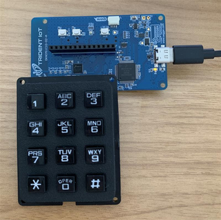
Keypad Physical Connection
To attach the optional 3×4 keypad to the Trident DKNCM11 board, place both the DKNCM11 and the keypad flat on the desk with their front faces upward and oriented so the text on both boards reads normally (facing north). Then rotate the DKNCM11 board 90 degrees counter-clockwise so that its top edge now points west.
With the boards in this orientation:
- The keypad’s pin header should be aligned with the bottom row of the DKNCM11’s pin socket.
- Insert the keypad so that its left-most pin aligns with the left-most position of the DKNCM11 bottom row.
- Fully seat the keypad header into the socket so that all pins are engaged.
This connection ensures that the keypad signals match the GPIO configuration expected by src/keypad.c.
Buttons and Keypad
| Button | Action | Description |
|---|---|---|
| BTN0 | Press | Hardware reset |
| BTN1 | Press | Simulate a manual deadbolt lock operation |
| BTN2 | Press | Simulate a manual deadbolt unlock operation |
| 0-9 | Press | Enter a PIN code digit |
| * | Press | Lock door as keypad operation, no PIN code required |
| # | Press | Unlock door as keypad operation, PIN code will be verified against user table |
LEDs
At boot the LEDs indicate network operations:
| LED | Behavior | Description |
|---|---|---|
| Green | On for 2 seconds | Device reboot and previously joined to a network |
| Green | Blink 100ms | When network rejoin attempt is made |
| Red | On for 2 seconds | Network search attempts exhausted |
| Blue | On for identify duration | Identify command received |
| Blue | Blink 3 times | Network search attempt started |
After boot the LEDs indicate door lock state:
| LED | Behavior | Description |
|---|---|---|
| Green | On solid | Door unlocked |
| Green | Flashing | Deadbolt moving to an unlocked position |
| Red | On solid | Door locked |
| Red | Flashing | Deadbolt moving to a locked position |
| Blue | On for identify duration | Identify command received |
Custom APP Tokens
This project contains an example of how to create custom APP tokens that can be used from the application and can be interacted with externally via elcap. As long as the project_app_tokens.h exists in the project src directory, the application tokens will be added to the project and the APP token definition file needed for interacting with these tokens via elcap will be generated into the build directory. The APP token definition file looks like T32CM11C_app_token_def.json.